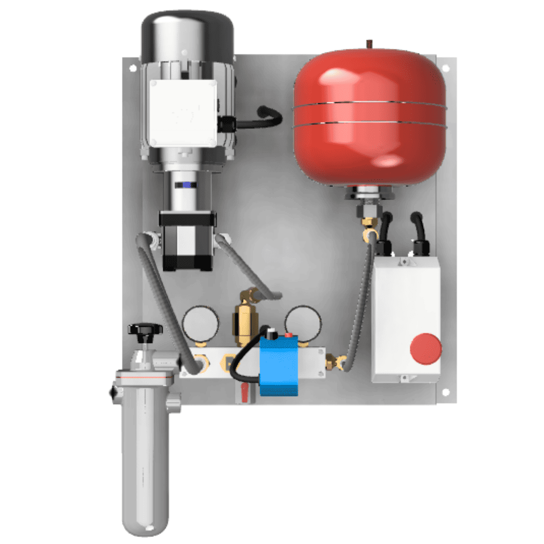
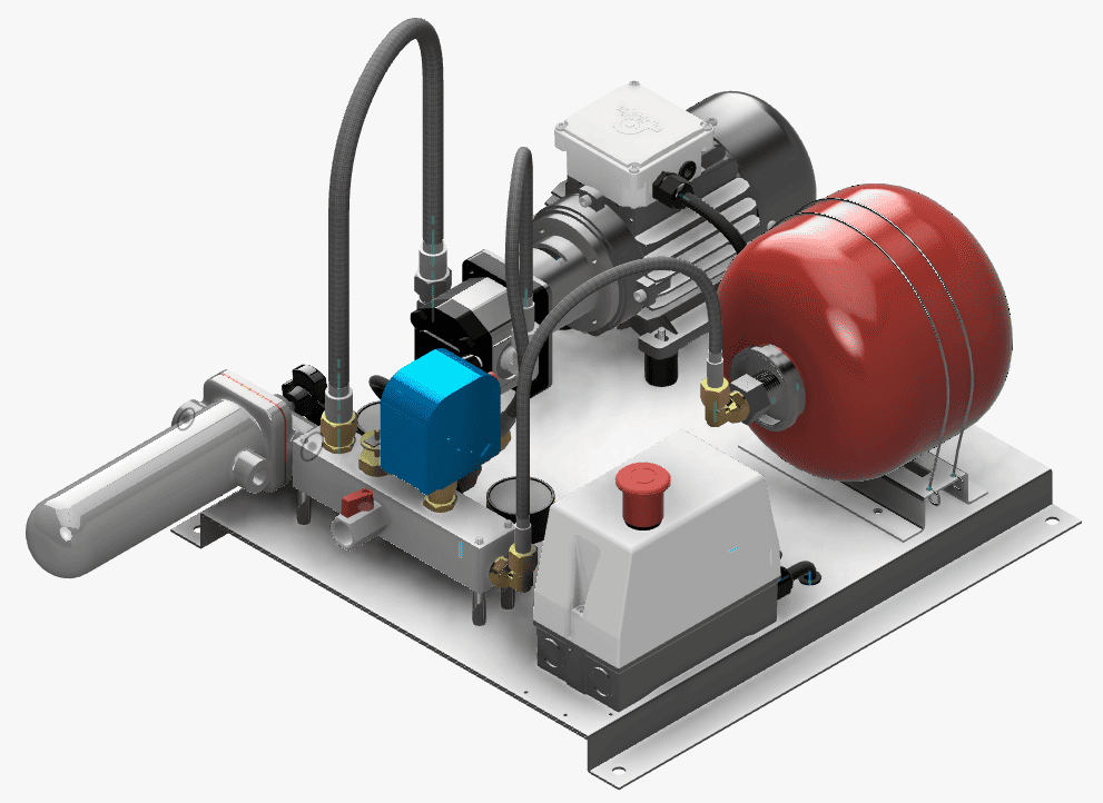
OIL TRANSFER PRESSURE UNITS – From 70l/h to 1500L/h – N
N: 1 pump
Inpro pressure units are equipment used to transfer liquid fuel such as diesel or HVO from a main tank to different consumption points through the pressurization of a line, for the supply of machinery that requires these fuels, such as generators (power generators) or burners for boilers in buildings.
.
There are several sizes and configurations of equipment, in which the flow rate that can control the equipment can vary (from 30l/h to 12,000 l/h), the maximum pressure at which they can work, with the possibility of redundancy in some components, and other parameters such as the type of power supply.
.
It can be Normal or Twin equipment that duplicates critical components to increase reliability.
.
Application area example
Small units (from 30l/h to 1,500l/h) can be used for:
- The supply of boilers in single-family houses.
- Community of neighbors buildings
- Small installations.
And large units (from 2,000l/h to 12,000l/h) can be applied in:
- Large buildings requiring 24h/7 electricity
- Data Centers
- Hospitals
- Airports
- Malls…
Applications & Specific Features
- Multiple burner, appliances or service tanks supplied with one GP pressure unit.
- Appliances installed at different heights.
- Modulating burners when using the Inpro Oil Burner Inlet Assembly (see Datasheet).
- Oil Supply installation using ‘dead leg’ pipework. GP unit does not need external controls.
- GP units operate on an internal pressure switch only pumping fuel when required.
- Pressure regulators may be required at oil inlet to burners/appliances.
- Limited suction lift may require GP unit to be sited near the oil tank.
Accessories and Adaptations
- Free voltage relay output to control from centralised Building Management System, in kit 3, 4 or 6 signals (2-thermal, motors 1 or 2 ON, low pressure and Leak safety ON).
- GSM alarm system by SMS messages, or connection to modem.
- Adaptation of Pressure Group for high pressure, working conditions of up to 6 Kg/cm2
- Leak collector trays with infrared detectors (standard in GP-800 and GP-1500).
- Modifications to adapt to specifically regulated environments with tropicalised equipment or ATEX.
- Solenoid valv
Caractéristiques techniques
| MODEL | GP-70 N | GP-130 N | GP-200 N | GP-300 N | GP-500 N | GP-800 N | GP-1500 N | |
|---|---|---|---|---|---|---|---|---|
| FLOW | l/h | 70 | 130 | 200 | 300 | 500 | 800 | 1500 |
| CONNECTION TO THE HYDRAULIC CIRCUIT (Ø THREAD / Ø mm) |
SUCTION | 1/2” F | 1/2” F | 1/2” F | 3/4” F | 3/4” F | 1” F | 1” F |
| DRIVE | 3/8” F | 3/8” F | 3/8” F | 1/2” F | 1/2” F | 1/2” F | 3/4” F | |
| POWER SUPPLY | VOLTS | 230/400 tri-phase* |
230/400 tri-phase* |
230/400 tri-phase |
230/400 tri-phase |
230/400 tri-phase |
| MOTOR POWER | C.V. | 1/4 | 1/3 | 1/3 | 1/3 | 1/2 | 3/4 | 1½ |
| KW | 0,18 | 0,25 | 0,25 | 0,25 | 0,37 | 0,55 | 1,1 | |
| MAX. PRESSURE | kg/cm2 | 3,5 | 3,5 | 3,5 | 4 | 4 | 4 | 4 |
| SAFETY VALVE OPENS AT: | kg/cm2 | 4 | 4 | 4 | 4,5 | 4,5 | 4,5 | 4,5 |
| MOTOR PROTECTION | IP | 55 | 55 | 55 | 55 | 55 | 55 | 55 |
– (*) Existent en version 230 monophasé (W)
– Niveau de son: 58 db (A)
GP Videos:
| Pressure switch regulation | GP troubleshooting |
GP70 GP 70 GP1500 GP 1500